GE SR750/760 Relay Tutorials - Part 4: Add XRIO Parameters And Link Them To Other Parameters In The Test Object
Welcome to the fourth part of GE SR750/760 Relay Tutorial series. In this tutorial, I will show you how to create Real, Enumeration, Boolean and Integer parameters and link them to other parameters.
If you haven't seen the previous tutorials, click the link below:
Now, open the test document that created from the previous tutorial (Part 3).

Add new blocks and parameters
Open the Test Object in the test document, expand the relay parameters node and right click on to system setup then click Add Block and rename it to Sensing the same in the EnerVista 750/760 Setup.

Now, add four parameters for current sensing. One string data type and three real data type. Rename those as per the image below.

Right click on to current sensing parameter or double click on it to open the Parameter Details dialog box to change the name, ID, formula and other settings. See the parameter details in the table below.

Once the current sensing parameters completed, try to do the remaining parameters in the sensing node. See the following parameters in the table below. If the parameters is not in the table like description, foreign ID or etc. leave it blank or by default. I will show you that in the other part of this tutorial series.
Once completed it should be like in the image below.

Add new Block under GE SR750/760 node and set the following parameters:

This should be look like in the image below.

Now, add new block under the new XRIO node and set the following parameters and this time we leave the enabled by default which is Yes. Because the XRIO node is already set to No or disabled. This mean XRIO node will not be displayed when we set the test object view to basic. You will notice that the XRIO node has a red X mark icon meaning this node and it's items will not shown in basic view mode.
Add the following parameters in the table below at the Power System node.
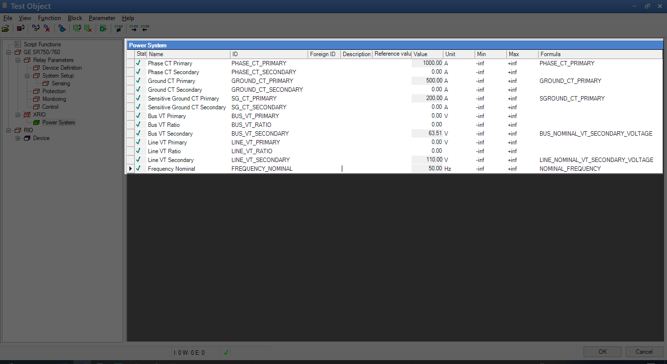
Once the Power System node and it's parameters created, it should be like in the image below.

Linking parameter to other parameters
I'm going to link first the Phase CT Primary at XRIO>Power System to Phase CT Primary value at Relay Parameters>System Setup>Sensing. Select Phase CT Primary parameter at XRIO>Power System node and click on to cell formula and right click inside of that cell then select Add Reference or hit Ctrl + I in the keyboard.

After right clicking or hitting Ctrl + I, the Insert Formula Reference dialog box will popup. In the dialog box, locate the Phase CT Primary parameter from Relay Parameter > System Setup > Sensing and select it.

The reference ID will display in the Ref ID textbox and it's value which is PHASE_CT_PRIMARY and 1000 A. Click OK to apply the selected parameter.

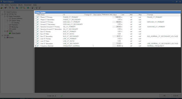
Do the same way for Ground CT Primary, Sensitive CT Primary, Bus VT Secondary, Line VT Secondary and Frequency Nominal. Once completed, that should look like in the image below.
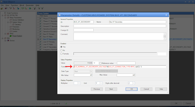
The rest of the parameters are requiring formula so I'm going to use script to write some formula like calculating the ratio of VT and also, I'm going to use condition formula at Bus VT Secondary because the VT connection type is not compensated. I'm going to multiply it by square root of 3 when Wye connected or 1 when Delta connected.

Then add = sign then right click on inside the textbox again then locate Wye under Relay Parameters> System Setup > Sensing > Bus VT Connection Type then click OK.

After that, add comma sign (,) then add sqrt(3) then comma sign (,) the 1 and add ) at the end of the formula. That should look like in the image below.
Make a formula in the script function editor
Now, let's write formula that calculate the ratio of the given VT Ratio. In the test object, click on to Script Functions node then copy the script below and paste it to the script function editor.

Then click Compile button to check if there's no errors and warnings in the script.

Let's use the GetVTRatio formula in the parameter formula. Select XRIO > Power System > Bus VT Ratio parameter and double click on to little black arrow to display it's parameter details. In the formula textbox, type GetVTRatio( and right click on it then locate the Bus VT Ratio parameter under Relay Parameters > System Setup > Sensing then click OK to add the selected parameter then type ) at the end. That should be look like the image below.
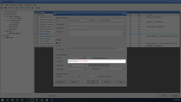
Then, click OK button. Bus VT Ratio must have a new value which is 100. Do the same way to Line VT Ratio and that must have a new value of 57.7.

We now have VT Ratio and VT Secondary. It's time to get the VT Primary using the formula below

Now, double click on to Bus VT Primary under the XRIO > Power System node to display the parameter details dialog box and right click on the formula textbox then locate the VT Secondary under the XRIO > Power System node than click OK

Then, type * (asterisk sign) then right click again on the formula textbox then select the Bus VT Ratio under the XRIO > Power System node then click OK and then click OK to close the parameter details dialog box. Make sure the cursor position is at the end of the formula before do the right click.

We have now Bus VT Primary value which is 11000.25 and we must use round off formula to make it 11000.00

That's it for now. In the next part I will show you how to link those parameters in the Device RIO function and also I will show you how to make this template flexible for the testing.

Summary
In this tutorial, we've learned the following
If you haven't seen the previous tutorials, click the link below:
Part 3: Setup Omicron Control Center (OCC) for Testing
GE SR750/760 Relay Tutorials
Now, open the test document that created from the previous tutorial (Part 3).

Add new blocks and parameters
Open the Test Object in the test document, expand the relay parameters node and right click on to system setup then click Add Block and rename it to Sensing the same in the EnerVista 750/760 Setup.

Now, add four parameters for current sensing. One string data type and three real data type. Rename those as per the image below.

Right click on to current sensing parameter or double click on it to open the Parameter Details dialog box to change the name, ID, formula and other settings. See the parameter details in the table below.

Once the current sensing parameters completed, try to do the remaining parameters in the sensing node. See the following parameters in the table below. If the parameters is not in the table like description, foreign ID or etc. leave it blank or by default. I will show you that in the other part of this tutorial series.
| GE SR750/760 > Relay Parameters > System Setup > Sensing | |||||||||||||||
|---|---|---|---|---|---|---|---|---|---|---|---|---|---|---|---|
| Parameter | Value | ||||||||||||||
| Current Sensing | |||||||||||||||
| ID | TITLE1 | ||||||||||||||
| Name | Current Sensing | ||||||||||||||
| Data Type | String | ||||||||||||||
| Formula | " " | ||||||||||||||
| Phase CT Primary | |||||||||||||||
| ID | PHASE_CT_PRIMARY | ||||||||||||||
| Name | Phase CT Primary | ||||||||||||||
| Value | 1000 | ||||||||||||||
| Reference value | 1000 | ||||||||||||||
| Data Type | Real | ||||||||||||||
| Min Value | 1 | ||||||||||||||
| Max Value | 50000 | ||||||||||||||
| Unit | A | ||||||||||||||
| Digits after decimal | 0 | ||||||||||||||
| Ground CT Primary | |||||||||||||||
| ID | GROUND_CT_PRIMARY | ||||||||||||||
| Name | Ground CT Primary | ||||||||||||||
| Value | 500 | ||||||||||||||
| Reference value | 500 | ||||||||||||||
| Data Type | Real | ||||||||||||||
| Min Value | 1 | ||||||||||||||
| Max Value | 50000 | ||||||||||||||
| Unit | A | ||||||||||||||
| Digits after decimal | 0 | ||||||||||||||
| Sensitive Ground CT Primary | |||||||||||||||
| ID | SGROUND_CT_PRIMARY | ||||||||||||||
| Name | Sensitive Ground CT Primary | ||||||||||||||
| Value | 200 | ||||||||||||||
| Reference value | 200 | ||||||||||||||
| Data Type | Real | ||||||||||||||
| Min Value | 1 | ||||||||||||||
| Max Value | 50000 | ||||||||||||||
| Unit | A | ||||||||||||||
| Digits after decimal | 0 | ||||||||||||||
| Bus VT Sensing | |||||||||||||||
| ID | TITLE2 | ||||||||||||||
| Name | Bus VT Sensing | ||||||||||||||
| Data Type | String | ||||||||||||||
| Formula | " " | ||||||||||||||
| Bus VT Connection Type | |||||||||||||||
| ID | BUS_VT_CONNECTION_TYPE | ||||||||||||||
| Name | Bus VT Connection Type | ||||||||||||||
| Data Type | Enumeration | ||||||||||||||
|
|||||||||||||||
| Value | Wye | ||||||||||||||
| Bus Nominal VT Secondary Voltage | |||||||||||||||
| ID | BUS_NOMINAL_VT_SECONDARY_VOLTAGE | ||||||||||||||
| Name | Bus Nominal VT Secondary Voltage | ||||||||||||||
| Value | 63.51 | ||||||||||||||
| Reference Value | 63.51 | ||||||||||||||
| Data Type | Real | ||||||||||||||
| Min Value | 50.0 | ||||||||||||||
| Max Value | 240.0 | ||||||||||||||
| Unit | V | ||||||||||||||
| Digits after decimal | 1 | ||||||||||||||
| Bus VT Ratio | |||||||||||||||
| ID | BUS_VT_RATIO | ||||||||||||||
| Name | Bus VT Ratio | ||||||||||||||
| Value | 100.0 : 1 | ||||||||||||||
| Reference Value | 100.0 : 1 | ||||||||||||||
| Data Type | String | ||||||||||||||
| Line VT Sensing | |||||||||||||||
| ID | TITLE3 | ||||||||||||||
| Name | Line VT Sensing | ||||||||||||||
| Data Type | String | ||||||||||||||
| Formula | " " | ||||||||||||||
| Line VT Connection | |||||||||||||||
| ID | LINE_VT_CONNECTION | ||||||||||||||
| Name | Line VT Connection | ||||||||||||||
| Data Type | Enumeration | ||||||||||||||
|
|||||||||||||||
| Value | An | ||||||||||||||
| Line Nominal VT Secondary Voltage | |||||||||||||||
| ID | LINE_NOMINAL_VT_SECONDARY_VOLTAGE | ||||||||||||||
| Name | Line Nominal VT Secondary Voltage | ||||||||||||||
| Value | 110.0 | ||||||||||||||
| Reference Value | 110.0 | ||||||||||||||
| Data Type | Real | ||||||||||||||
| Min Value | 50.0 | ||||||||||||||
| Max Value | 240.0 | ||||||||||||||
| Unit | V | ||||||||||||||
| Digits after decimal | 1 | ||||||||||||||
| Line VT Ratio | |||||||||||||||
| ID | LINE_VT_RATIO | ||||||||||||||
| Name | Line VT Ratio | ||||||||||||||
| Value | 57.7 : 1 | ||||||||||||||
| Reference Value | 57.7 : 1 | ||||||||||||||
| Data Type | String | ||||||||||||||
| Power System | |||||||||||||||
| ID | TITLE4 | ||||||||||||||
| Name | Power System | ||||||||||||||
| Data Type | String | ||||||||||||||
| Formula | " " | ||||||||||||||
| Nominal Frequency | |||||||||||||||
| ID | NOMINAL_FREQUENCY | ||||||||||||||
| Name | Nominal Frequency | ||||||||||||||
| Data Type | Real | ||||||||||||||
| Value | 50 | ||||||||||||||
| Reference value | 50 | ||||||||||||||
| Data Type | Real | ||||||||||||||
| Min Value | 25 | ||||||||||||||
| Max Value | 60 | ||||||||||||||
| Unit | Hz | ||||||||||||||
| Digits after decimal | 0 | ||||||||||||||
| Phase Sequence | |||||||||||||||
| ID | PHASE_SEQUENCE | ||||||||||||||
| Name | Phase Sequence | ||||||||||||||
| Data Type | Enumeration | ||||||||||||||
|
|||||||||||||||
| Value | ABC | ||||||||||||||
| Cost of energy | |||||||||||||||
| ID | COST_OF_ENERGRY | ||||||||||||||
| Name | Cost of energy | ||||||||||||||
| Data Type | Real | ||||||||||||||
| Value | 5.0 | ||||||||||||||
| Reference value | 5.0 | ||||||||||||||
| Data Type | Real | ||||||||||||||
| Min Value | 1.0 | ||||||||||||||
| Max Value | 25.0 | ||||||||||||||
| Unit | cents/kWh | ||||||||||||||
| Digits after decimal | 1 | ||||||||||||||
Once completed it should be like in the image below.

Add new Block under GE SR750/760 node and set the following parameters:

| GE SR750/760 > XRIO | |
|---|---|
| XRIO | |
| ID | XRIO |
| Name | XRIO |
| Enabled | No |
This should be look like in the image below.

Now, add new block under the new XRIO node and set the following parameters and this time we leave the enabled by default which is Yes. Because the XRIO node is already set to No or disabled. This mean XRIO node will not be displayed when we set the test object view to basic. You will notice that the XRIO node has a red X mark icon meaning this node and it's items will not shown in basic view mode.
| GE SR750/760 > XRIO > Power System | |
|---|---|
| Power System | |
| ID | POWER_SYSTEM |
| Name | Power System |
Add the following parameters in the table below at the Power System node.
| GE SR750/760 > XRIO > Power System | |
|---|---|
| Parameter | Value |
| Phase CT Primary | |
| ID | PHASE_CT_PRIMARY |
| Name | Phase CT Primary |
| Unit | A |
| Phase CT Secondary | |
| ID | PHASE_CT_SECONDARY |
| Name | Phase CT Secondary |
| Unit | A |
| Ground CT Primary | |
| ID | GROUND_CT_PRIMARY |
| Name | Ground CT Primary |
| Unit | A |
| Ground CT Secondary | |
| ID | GROUND_CT_SECONDARY |
| Name | Ground CT Secondary |
| Unit | A |
| Sensitive Ground CT Primary | |
| ID | SG_CT_PRIMARY |
| Name | Sensitive Ground CT Primary |
| Unit | A |
| Sensitive Ground CT Secondary | |
| ID | SG_CT_SECONDARY |
| Name | Sensitive Ground CT Secondary |
| Unit | A |
| Bus VT Primary | |
| ID | BUS_VT_PRIMARY |
| Name | Bus VT Primary |
| Unit | V |
| Bus VT Ratio | |
| ID | BUS_VT_RATIO |
| Name | Bus VT Ratio |
| Bus VT Secondary | |
| ID | BUS_VT_SECONDARY |
| Name | Bus VT Secondary |
| Unit | V |
| Line VT Primary | |
| ID | LINE_VT_PRIMARY |
| Name | Line VT Primary |
| Unit | V |
| Line VT Ratio | |
| ID | LINE_VT_RATIO |
| Name | Line VT Ratio |
| Line VT Secondary | |
| ID | LINE_VT_SECONDARY |
| Name | Line VT Secondary |
| Unit | V |
| Frequency Nominal | |
| ID | FREQUENCY_NOMINAL |
| Name | Frequency Nominal |
| Unit | Hz |
Once the Power System node and it's parameters created, it should be like in the image below.

Linking parameter to other parameters
I'm going to link first the Phase CT Primary at XRIO>Power System to Phase CT Primary value at Relay Parameters>System Setup>Sensing. Select Phase CT Primary parameter at XRIO>Power System node and click on to cell formula and right click inside of that cell then select Add Reference or hit Ctrl + I in the keyboard.

After right clicking or hitting Ctrl + I, the Insert Formula Reference dialog box will popup. In the dialog box, locate the Phase CT Primary parameter from Relay Parameter > System Setup > Sensing and select it.

The reference ID will display in the Ref ID textbox and it's value which is PHASE_CT_PRIMARY and 1000 A. Click OK to apply the selected parameter.

Do the same way for Ground CT Primary, Sensitive CT Primary, Bus VT Secondary, Line VT Secondary and Frequency Nominal. Once completed, that should look like in the image below.
The rest of the parameters are requiring formula so I'm going to use script to write some formula like calculating the ratio of VT and also, I'm going to use condition formula at Bus VT Secondary because the VT connection type is not compensated. I'm going to multiply it by square root of 3 when Wye connected or 1 when Delta connected.
BUS_NOMINAL_VT_SECONDARY_VOLTAGE * iif(BUS_VT_CONNECTION_TYPE=WYE, Sqrt(3),1)To do that, right click on to Bus VT Secondary parameter under XRIO > Power System then select Details to display Parameter Details. In the formula textbox, BUS_NOMINAL_VT_SECONDARY_VOLTAGE is already in there. Add * iif( then right click on inside of the formula textbox then locate Bus VT Connection Type under the Relay Parameters > System Setup > Sensing then click OK.

Then add = sign then right click on inside the textbox again then locate Wye under Relay Parameters> System Setup > Sensing > Bus VT Connection Type then click OK.

After that, add comma sign (,) then add sqrt(3) then comma sign (,) the 1 and add ) at the end of the formula. That should look like in the image below.

Now, let's write formula that calculate the ratio of the given VT Ratio. In the test object, click on to Script Functions node then copy the script below and paste it to the script function editor.
1 2 3 4 5 6 7 8 9 10 11 12 | Function GetVTRatio(Ratio As String) As Double Dim rs As String() = Ratio.Split(":") If Ubound(rs) = 1 Then Return Val(rs(Lbound(rs)).Trim) ElseIf Ubound(rs) = 2 Then Dim u As Double = val(rs(Lbound(rs)).Trim) Dim l As Double = val(rs(Ubound(rs)).Trim) Return u / l Else Return Val(Ratio.Trim) End If End Function |

Then click Compile button to check if there's no errors and warnings in the script.

Let's use the GetVTRatio formula in the parameter formula. Select XRIO > Power System > Bus VT Ratio parameter and double click on to little black arrow to display it's parameter details. In the formula textbox, type GetVTRatio( and right click on it then locate the Bus VT Ratio parameter under Relay Parameters > System Setup > Sensing then click OK to add the selected parameter then type ) at the end. That should be look like the image below.

Then, click OK button. Bus VT Ratio must have a new value which is 100. Do the same way to Line VT Ratio and that must have a new value of 57.7.

We now have VT Ratio and VT Secondary. It's time to get the VT Primary using the formula below
Now, double click on to Bus VT Primary under the XRIO > Power System node to display the parameter details dialog box and right click on the formula textbox then locate the VT Secondary under the XRIO > Power System node than click OK

Then, type * (asterisk sign) then right click again on the formula textbox then select the Bus VT Ratio under the XRIO > Power System node then click OK and then click OK to close the parameter details dialog box. Make sure the cursor position is at the end of the formula before do the right click.

We have now Bus VT Primary value which is 11000.25 and we must use round off formula to make it 11000.00

That's it for now. In the next part I will show you how to link those parameters in the Device RIO function and also I will show you how to make this template flexible for the testing.

Summary
In this tutorial, we've learned the following
- Adding of XRIO block
- Adding of XRIO parameters with different data type
- Linking parameter to other parameters
- Making formula in the script function editor
- Using formula in the parameter formula textbox
See you next time.
Comments
Post a Comment